Arduino Project 01 - Get to Know Your Tools
So recently someone in my neighborhood was giving away an Arudino along with some other supplies to go along with it for free. My girlfriend reached out and was lucky enough to get it all for free! What I think I got was the contents of the Arduino starter kit. It comes with an Arduino uno, a small bread board, a box full of wires, resistors, LEDs and more, and finally it comes with a project book that contains 15 educational projects for Arduino that I’m going to try to complete.
I work as a web developer, and I have a bachelors in computer science, but I have never taken a class on anything about electric engineering, computer hardware, circuitry or even taken a single physics class. The extent of my hardware background is that I assembled the parts of the desktop computer that I’m going to use in recording this series. So I thought I would make a fun and educational series of me completing the 15 projects so that you can learn along with me as I discover how to use this Arduino. I will try to follow closely along with the book and might even read straight from the book, but also to add in my own findings and thoughts from time to time.
So let’s dive right into it with project one, “Get to Know Your Tools”, where we make a simple circuit with some switches, an LED, and a resistor. This is probably the first electric circuit I had ever made besides trying to make a circuit out of a potato in elementary school.
I’m going to need to review some of the basics before building this circuit.
A Couple Things About Circuits
The book describes electrical current flow as a rock slide. And there are three parts: Current, Voltage, and Resistance. Current is like the rocks at the top of the mountain, the more rocks the more energy being carried down the circuit. Voltage is the height of the cliff, the higher the cliff also the more energy the rocks will release when they hit the bottom. Lastly we have the resistance, which might be the trees or debris in the way of the rocks that slow them down as they fall. All of this together represents Ohm’s law which states that Voltage equals current times resistance.
What’s a Breadboard?
Basically a bread board is basically a plastic board covered in tiny holes that go to metal strips. They are used to quickly prototype circuits by inserting wires and electrical components into the holes, and don’t require any soldering or PCB design.
Circuit Drawings
I’ve been watching a few youtube videos about making circuits and everyone says that you should always design your circuit out on paper or at least make a diagram on your computer before you go to make it. Kinda like how in software you should be able to explain the algorithm in plain language before you implement it in code.
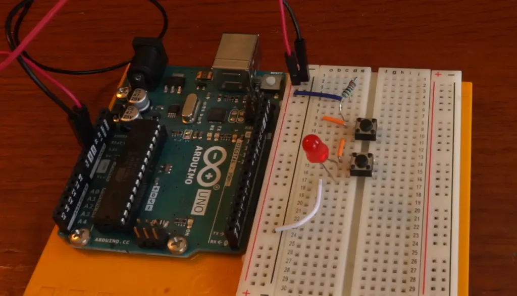
And with all of that I went ahead and made three of the example circuits from the project book. A few learnings I had was that a pair of tweezers helps a ton with placing the wires, and also that it helps to have all the parts of your circuit picked out before you start building it.
Heres one of the circuits from project one.